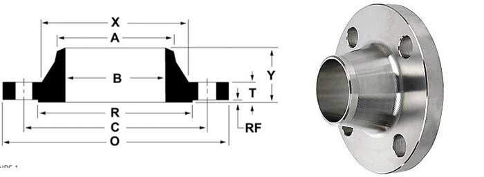
ASME B16.5 Class 150 Weld Neck Flange
ASME B16.5 is a standard developed by the American Society of Mechanical Engineers for pipe flanges and flange connections. This standard provides detailed specifications for flanges of various sizes, pressure levels, materials, and surface types to meet the needs of various industrial applications. ASME B16.5 Class 150 weld neck flange, as an important type, is widely used in industries such as petroleum, chemical, natural gas, power, pharmaceuticals, and food.
Specification
| Shape Type | Regular and Long Neck |
| Sealing Face | RF, FF, FTJ |
| Size Range | 1/2″ – 60″/ DN15 – DN1200 |
| Pressure Rating | Class 150, 300, 600, 900, 1500, 2500lb |
| Standard | ASME B16.5, ASME B16.47 Series A/B |
| Alloy Steel | ASTM A182 F11 / 12 / 5 / 9 / 91 / 92 |
| Stainless Steel | ASTM A182 F304/304L/304H, 316/316L, 310S, 317,347,904L |
| Duplex Stainless Steel | ASTM A182 F51, F53, F44 |
Material Grade of ASTM A182 Flange
Alloy Material For Class 150 Weld Neck Flange
ASTM A182 F11 is a relatively common alloy flange, which is divided into three grades, each with different chemical composition and mechanical property requirements, to accommodate different environments for pipeline systems.
Chemical Composition
| CHEMICAL | LIMITS | C | Mn | P | S | Si | Cr | Mo |
| ASTM A182 F11 CL1 | MIN | 0.05 | 0.30 | 0.50 | 1.00 | 0.44 | ||
| MAX | 0.15 | 0.60 | 0.03 | 0.03 | 1.00 | 0.65 | ||
| ASTM A182 F11 CL2 | MIN | 0.10 | 0.30 | 0.50 | 1.00 | 0.44 | ||
| MAX | 0.20 | 0.80 | 0.04 | 0.04 | 1.00 | 0.65 | ||
| ASTM A182 F11 CL3 | MIN | 0.05 | 0.30 | 0.50 | 1.00 | 0.44 | ||
| MAX | 0.15 | 0.60 | 0.03 | 0.03 | 1.00 | 0.65 |
Mechanical Properties
| MATERIAL | ASTM A182 F11 CL1 | ASTM A182 F11 CL2 | ASTM A182 F11 CL3 |
| T.S (MPA) | 415 min | 485 min | 515 min |
| Y.S (MPA) | 205 min | 275 min | 310 min |
| EL % | 20 min | 20 min | 20 min |
| R/A % | 45 min | 30 min | 30 min |
| HARDNESS | 121-174 | 143-207 | 150-207 |
Alloy steel class 150 weld neck flange have strong corrosion resistance, high temperature resistance, excellent sealing performance, and rigid and elastic requirements, and are widely used in various industrial fields.
ASTM A182 Stainless Steel Flange
ASTM A182 F304/304H/304L are all austenitic stainless steel materials, which are commonly used in the raw materials of ASTM A182 class 150 weld neck flange. Their prices are relatively cheaper than stainless steel materials such as 316 and 904, so they are widely used in pipeline systems.
Chemical Composition
| CHEMICAL | LIMITS | C | Mn | P | S | Si | Ni | Cr | N |
| ASTM A182 F304 | MIN | 8.00 | 18.00 | ||||||
| MAX | 0.08 | 2.00 | 0.045 | 0.030 | 1.00 | 11.00 | 20.00 | 0.10 | |
| ASTM A182 F304L | MIN | 8.00 | 18.00 | ||||||
| MAX | 0.03 | 2.00 | 0.045 | 0.030 | 1.00 | 13.00 | 20.00 | 0.10 | |
| ASTM A182 F304H | MIN | 0.04 | 8.00 | 18.00 | |||||
| MAX | 0.10 | 2.00 | 0.045 | 0.030 | 1.00 | 11.00 | 20.00 |
Mechanical Properties
| MATERIAL | T.S (MPA) | Y.S (MPA) | EL % | R/A % |
| ASTM A182 F304 | 515 min | 205 min | 30 min | 50 min |
| ASTM A182 F304L | 485 min | 170 min | 30 min | 50 min |
| ASTM A182 F304H | 515 min | 205 min | 30 min | 50 min |
Duplex Stainless Steel Class 150 Weld Neck Flange
ASTM A182 F51/53/55 is a duplex stainless steel that is commonly used for forging ASTM A182 class 150 weld neck flange. Duplex steel is more commonly used in pipelines used in some special environments, where higher material requirements are imposed, and it can play a greater role.
Chemical Composition
| CHEMICAL | LIMITS | C | Mn | P | S | Si | Ni | Cr | Mo | N | Cu |
| ASTM A182 F51 | MIN | 4.50 | 21.00 | 2.50 | 0.08 | ||||||
| MAX | 0.03 | 2.00 | 0.030 | 0.020 | 1.00 | 6.50 | 23.00 | 3.50 | 0.20 | ||
| ASTM A182 F53 | MIN | 6.00 | 24.00 | 3.00 | 0.24 | ||||||
| MAX | 0.03 | 1.20 | 0.035 | 0.020 | 0.80 | 8.00 | 26.00 | 5.00 | 0.32 | 0.50 |
Mechanical Properties
| MATERIAL | ASTM A182 F51 | ASTM A182 F53 |
| T.S (MPA) | 620 min | 800 min |
| Y.S (MPA) | 450 min | 550 min |
| EL % | 25 min | 25 min |
| R/A % | 45 min | 15 min |
| HARDNESS | 310 max |
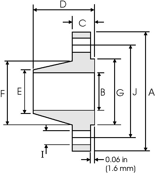
Class 150 Weld Neck Flange Dimension List

| Pipe | Flange Data | Hub Data | Raised Face | Drilling Data | Weigh | |||||||
Size | A | B | C | D | E | F | G | H | I | J | W | |
| Ouside | Overall | Inside | Flange Thickness min | Overall Length | Diameter at Weld Bevel | Huh Diameter | Face Diameter | Number of Holes | Bolt Hole Diameter | Diameter of Circle of Holes | kg/ piece | |
| mm | mm | mm | mm | mm | mm | mm | mm | in mm | in mm | |||
| 1/2 | 0.84 21.3 | 3.5 88.9 | 0.62 15.7 | 0.44 11.2 | 1.88 47.8 | 0.84 21.3 | 1.19 30.2 | 1.38 35.0 | 4 | 0.62 15.7 | 2.38 60.45 | 0.48 |
| 3/4 | 1.05 26.7 | 3.88 98.6 | 0.82 20.8 | 0.50 12.7 | 2.06 52.3 | 1.05 28.7 | 1.50 38.1 | 1.69 42.9 | 4 | 0.62 15.7 | 2.75 69.85 | 0.71 |
| 1 | 1.315 33.4 | 4.25 108.0 | 1.05 26.7 | 0.56 14.2 | 2.19 55.6 | 1.32 33.5 | 1.94 49.3 | 2.0 50.8 | 4 | 0.62 15.7 | 3.12 79.25 | 1.01 |
| 1-1/4 | 1.66 42.2 | 4.62 117.3 | 1.38 35.1 | 0.62 15.7 | 2.25 57.15 | 1.66 42.2 | 2.31 58.7 | 2.50 63.50 | 4 | 0.62 15.7 | 3.50 88.9 | 1.33 |
| 1-1/2 | 1.90 48.3 | 5.0 127.0 | 1.61 40.9 | 0.69 17.5 | 2.44 62.0 | 1.90 48.3 | 2.56 65.0 | 2.88 73.15 | 4 | 0.62 15.7 | 3.88 98.6 | 1.72 |
| 2 | 2.375 60.3 | 6.0 152.4 | 2.07 52.8 | 0.75 19.1 | 2.50 63.5 | 2.38 60.45 | 3.06 77.70 | 3.62 91.9 | 4 | 0.75 19.1 | 4.75 120.7 | 2.58 |
| 2-1/2 | 2.875 73.0 | 7.0 177.8 | 2.47 62.7 | 0.88 22.4 | 2.75 69.85 | 2.88 73.15 | 3.560 90.40 | 4.12 104.6 | 4 | 0.75 19.1 | 5.5 139.7 | 4.11 |
| 3 | 3.50 88.9 | 7.50 190.5 | 3.07 78.0 | 0.94 23.9 | 2.75 69.85 | 3.50 88.9 | 4.25 108.0 | 5.0 127.0 | 4 | 0.75 19.1 | 6.0 152.4 | 4.92 |
| 3-1/2 | 4.0 101.6 | 8.50 215.9 | 3.55 90.2 | 0.94 23.9 | 2.81 71.40 | 4.0 101.6 | 4.81 122.2 | 5.5 139.7 | 8 | 0.75 19.1 | 7.0 177.8 | 6.08 |
| 4 | 4.50 114.3 | 9.0 228.6 | 4.03 102.4 | 0.94 23.9 | 3.0 76.20 | 4.5 114.3 | 5.31 134.0 | 6.19 157.2 | 8 | 0.75 19.1 | 7.5 190.5 | 6.84 |
| 5 | 5.563 141.3 | 10.0 254.0 | 5.05 128.3 | 0.94 23.9 | 3.5 88.90 | 5.56 141.2 | 6.44 163.6 | 7.31 185.7 | 8 | 0.88 22.4 | 8.5 215.9 | 8.56 |
| 6 | 6.625 168.3 | 11.00 279.4 | 6.07 154.2 | 1.0 25.4 | 3.5 88.90 | 6.63 168.4 | 7.56 192.0 | 8.5 215.9 | 8 | 0.88 22.4 | 9.5 241.3 | 10.6 |
| 8 | 8.625 219.1 | 13.5 342.9 | 7.98 202.7 | 1.12 28.4 | 4.0 101.6 | 8.63 219.2 | 9.69 246.1 | 10.62 269.7 | 8 | 0.88 22.4 | 11.75 298.5 | 17.6 |
| 10 | 10.75 273.0 | 16.0 406.4 | 10.02 254.5 | 1.19 30.2 | 4.0 101.6 | 10.75 273.0 | 12.0 304.8 | 12.75 323.8 | 12 | 1.0 25.4 | 14.25 362.0 | 24.0 |
| 12 | 12.75 323.8 | 10.0 482.6 | 12.0 304.8 | 1.25 31.75 | 4.5 114.3 | 12.75 323.8 | 14.38 365.3 | 15.0 381.0 | 12 | 1.0 25.4 | 17.0 431.8 | 36.5 |
| 14 | 14.0 355.6 | 21.0 533.4 | 1.38 35.1 | 5.0 127.0 | 14.0 355.6 | 15.75 400.1 | 16.25 412.7 | 12 | 1.12 28.4 | 18.75 476.3 | 48.4 | |
| 16 | 16.0 406.4 | 23.5 506.9 | 1.44 36.6 | 5.0 127.0 | 16.0 406.4 | 18.0 475.2 | 18.50 469.9 | 16 | 1.12 28.4 | 21.25 539.8 | 60.6 | |
| 18 | 18.0 457.2 | 25.0 635.0 | 1.56 39.6 | 5.5 139.7 | 18.0 457.2 | 19.88 505.0 | 21.0 533.4 | 16 | 1.25 31.75 | 22.75 577.9 | 68.3 | |
| 20 | 20.0 508.0 | 27.5 698.5 | 1.69 42.9 | 5.69 144.5 | 20.0 508.0 | 22.0 558.8 | 23.0 584.2 | 20 | 1.25 31.75 | 25.0 635.0 | 84.5 | |
| 24 | 24.0 609.6 | 32.0 812.8 | 1.88 47.8 | 6.0 152.4 | 24.0 609.6 | 26.12 663.4 | 27.25 692.1 | 20 | 1.38 35.1 | 29.5 749.3 | 115 | |
Notes
1) Dimension B corresponds to the pipe inside diameter. Values quoted assume 40S/Standard wall thickness.
2) Weights are based on manufacturer’s data and are approximate .
3) Flat face flanges may be provided at full thickness, C, or with raised face removed (the latter is nonstandard).
4) The blank space needs to be provided by purchaser.
5) If you need class 300 ,600 ,900 ,1500 ,2500 flange dimensions & weight,please contact us.
